Last weekend, I decided to build an Ambilight kit to use with my HTPC (a Raspberry Pi with OpenElec 4.0.5).
In a couple of articles, I will show you the steps I followed for hardware and software installation.
The hardware
In this first article, we will start from the components needed. In my case, I purchased everything from Adafruit:
2x 12mm Diffused Thin Digital RGB LED Pixels (Strand of 25)
1x 5V 2A (2000mA) switching power supply – UL Listed
1x Female DC Power adapter – 2.1mm jack to screw terminal block
1x Breadboarding wire bundle
I purchased two strands of leds, because I was not sure of how many leds I really needed. In the end, I used all of them for my 32 inches TV. There are other types of leds if you prefer (pixel strip), but be sure they have at least the WS2801 chip that handle 24bit colors.
The power supply is necessary to power the leds, because the raspberry cannot do that by its own. To be honest, if you like, you can buy a stronger power supply (4a at least) to also power up the Raspberry Pi. You have to use the GPIO instead of the mini USB adapter and is not a good choice in my opinion, because, via the GPIO, there is no backward protection (here is a discussion on the topic).
I chose than to start with two separated power supplies. Remember also to check the power supply connector, so you will not end up like me, and have to buy another one with the correct connector for my country 🙂
In a future post, if there is interest, I will describe my solution to end up with just one power supply.
Assembling the pieces
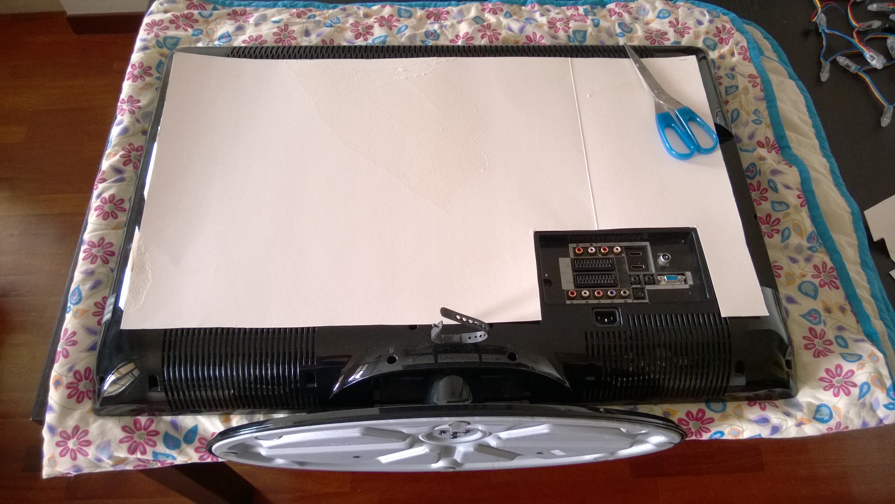
Now the fun part, let us take our TV on the table and start to hack it.
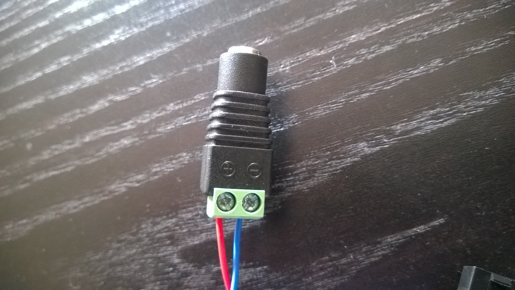
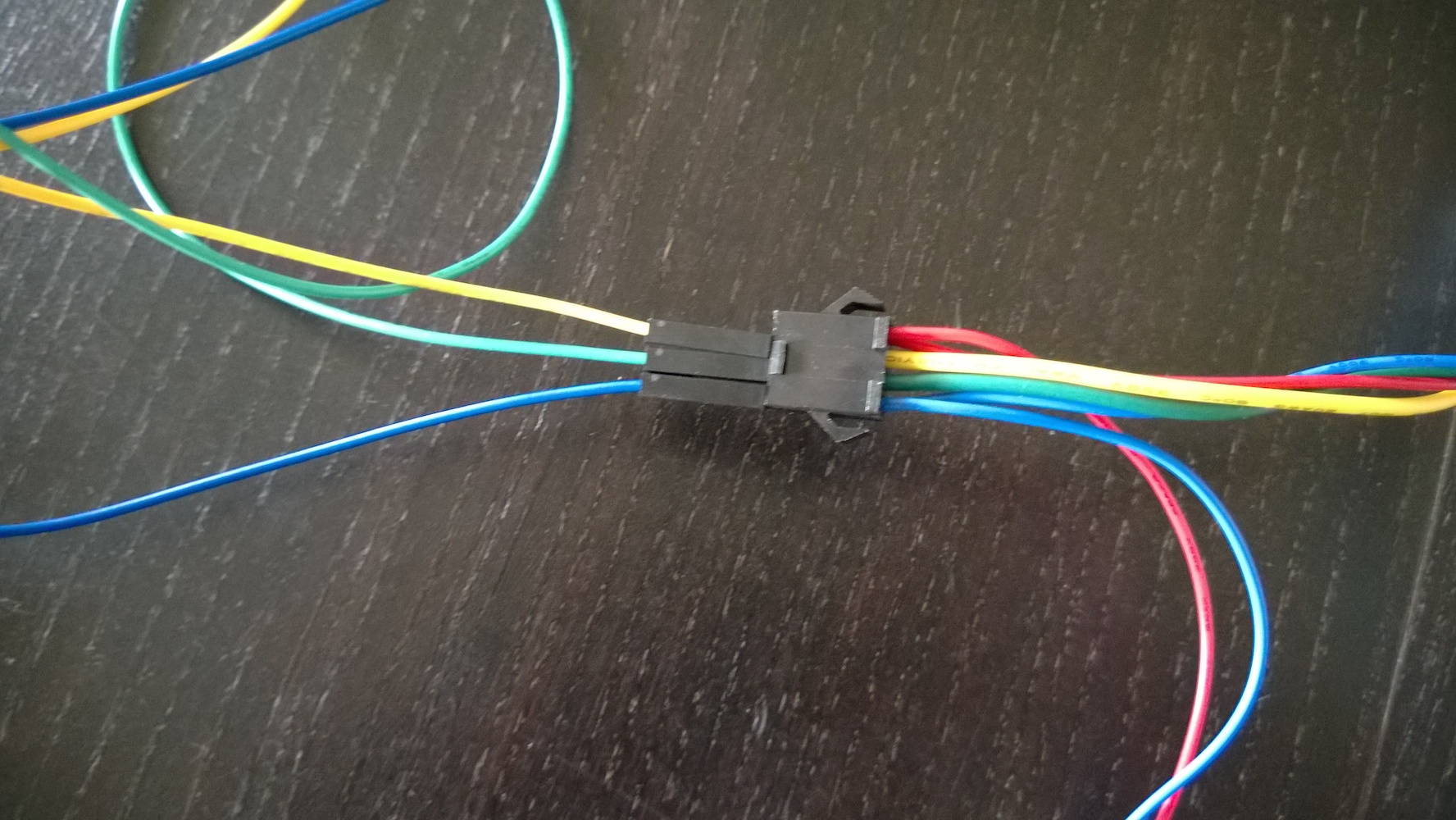
First, we prepare the leds and connectors that we will then attach to the back of our TV. Just connect together the led stripes (two in my case) and on the male end, connect the female DC power adapter like in the photo below:

With the leds I used, the red wire must be connected with plus sign (+) of the DC power adapter, while the blue one on the minus sign (-). Be sure to check how your leds should be wired before frying everything.
To attach the leds on the back of the TV, I used a cardboard with double-sided tape. I found it handy for taking the measures and in the case I need to remove and re-attach it.
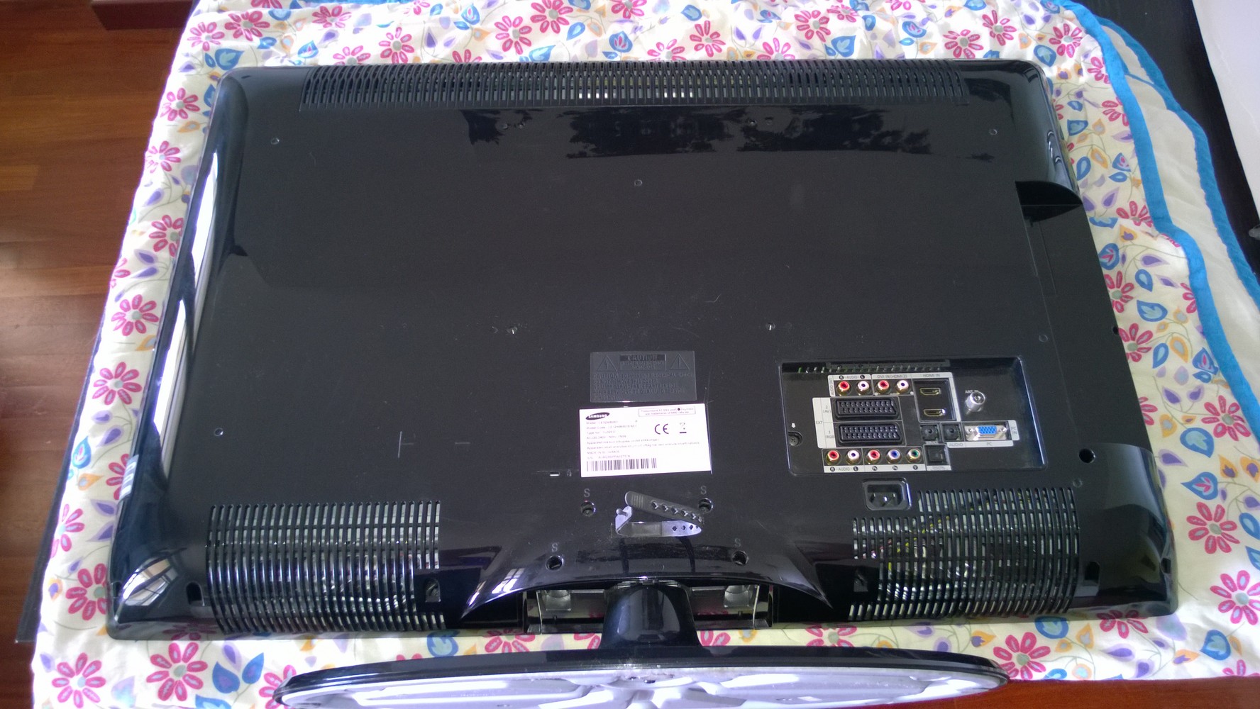
Take the measures and cut it to cover a little less than the TV’s borders. Remember to leave room for vents and back connectors:
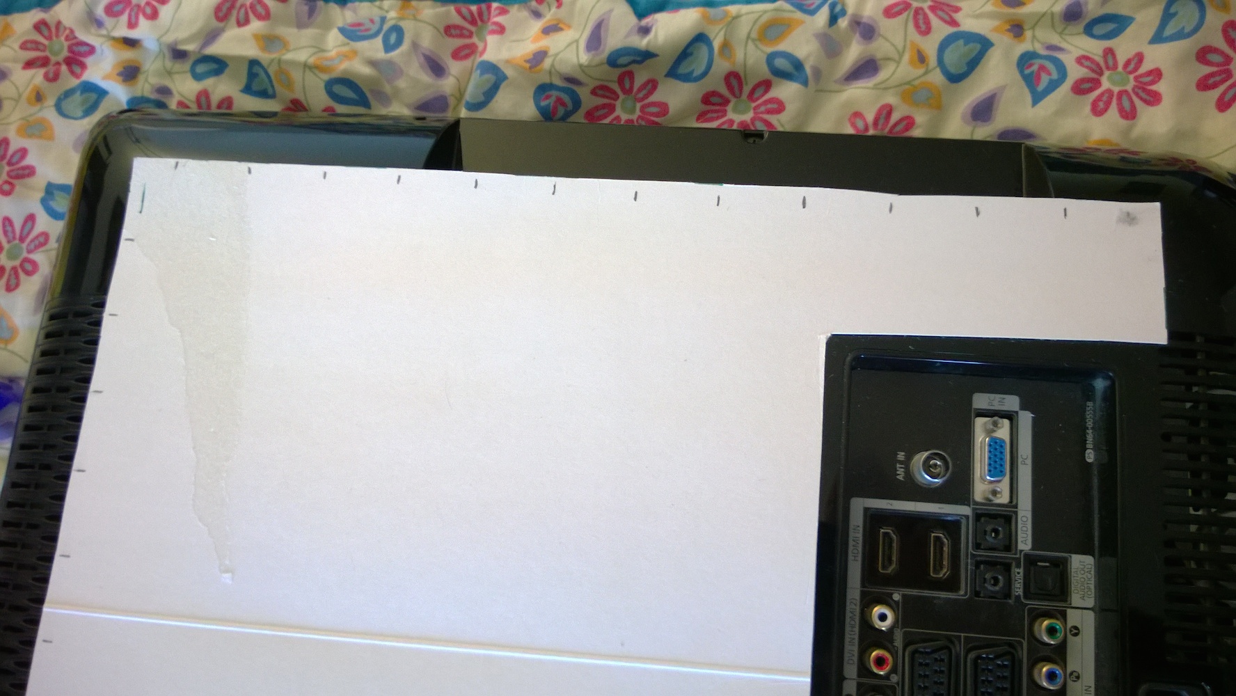
Now it is time for some math, because we need to distribute equally the leds across the borders of the TV. I did not count the bottom border, because my TV is not hanging on the wall, so do your adjustments just in case (you may also need to increase the numbers of leds)
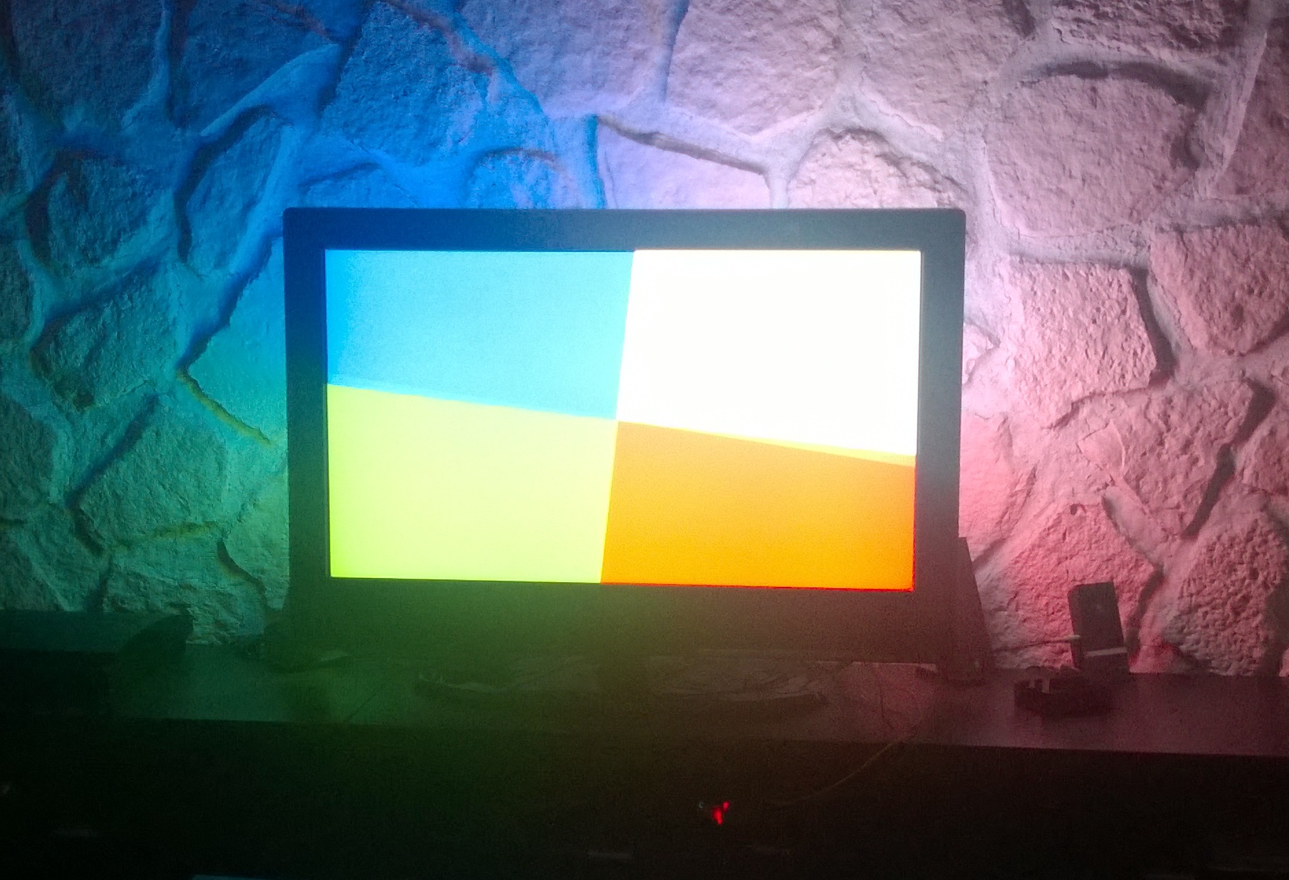
Measure and sum the three borders and then divide for 50. I end up with a led every 2.47 cm. If, like me, you want two leds on the top angles, you will need to do some adjustments and start drawing marks from one of them. At the end, you should have something like that:
Now it is time to attach the leds. I used two stripes of the same double-sided tape used for the cardboard, one on the bottom and one on the top of the them, and it worked just fine. The led are kept firmly in place without having to build any complex infrastructure to hold them.

Wiring the Raspberry Pi
Now that we have the leds mounted, we need to connect the wires to the raspberry’s GPIOs.

Based on this diagram from Boblight’s source code, I just connected the two wires for data and the one for ground, so leave out the red one (it is the 5v).
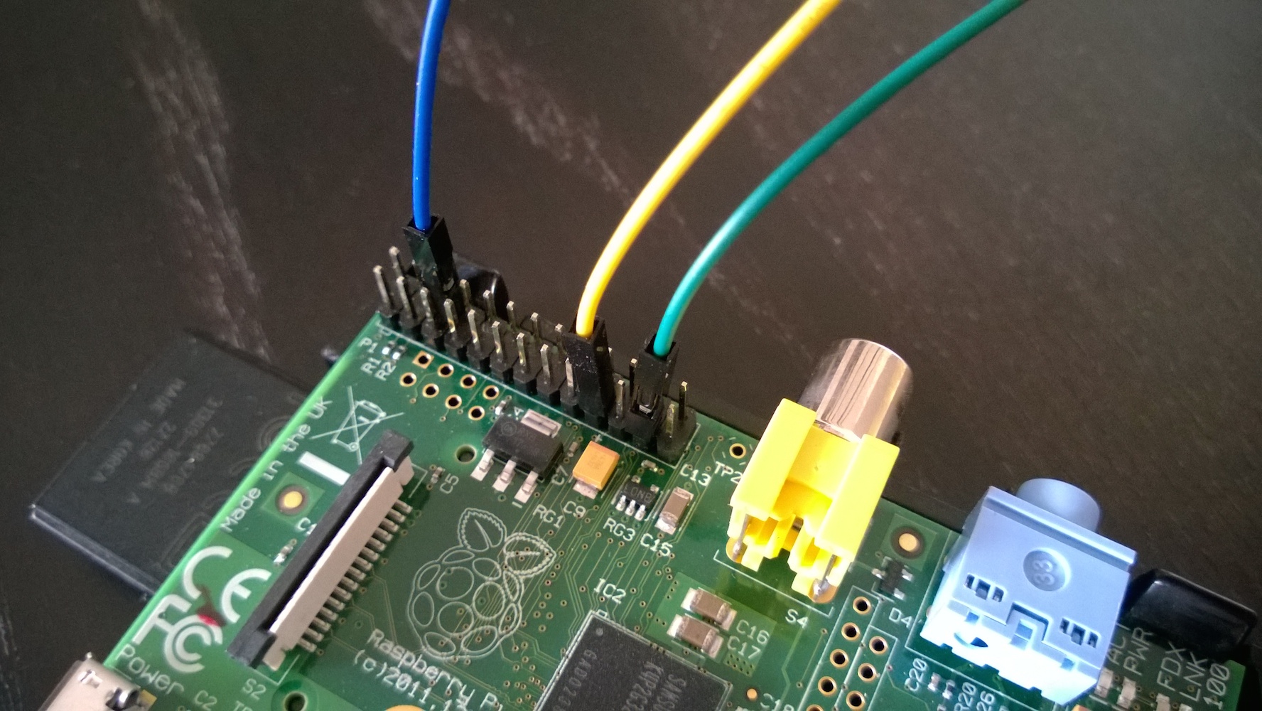
As you can see from the photos, the ground connector is inverted respect to the one in the diagram, so remember to look at the specs of your leds before connecting it.
Now that we have assembled all the pieces, we can proceed to the software part. In the next post we will see how to install and configure the software to handle the leds with XBMC.
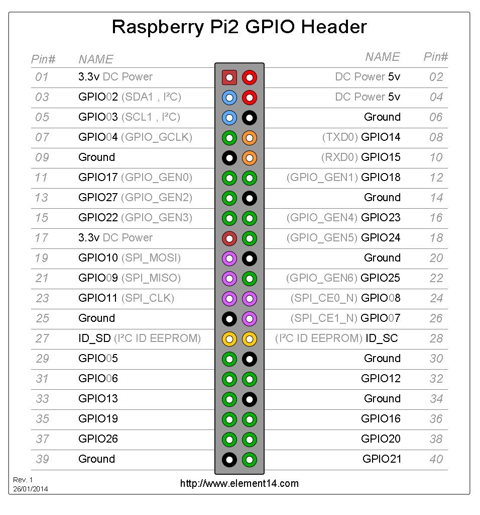
Update for Raspberry pi2
As posted in comments by user Chaves, the pins to use are different from the first raspberry. Use pin 19 (MOSI) and 23 (SCLK) like in the photo below